
Smart Home Components

Next, I need a Micro Processing Unit (MPU), Micro-controller (MCU) and the software.

After some design considerations, I have decided the brain of my system shall be a Raspberry PI.
  1. Raspberry is easily available. I have purchased mine at Taobao for less than S$70. It comes with a casing, power supply, 3xheat sinks, fan and a 16GB micro SD. This is the cheapest I can find.
  2. There are so many documentations, videos and websites on Raspberry Pi. 
  3. I watched a youtube clip showing Google Home assistant can be easily installed on a Pi. That sealed my decision to choose Raspberry Pi. 
The next piece shall be the automation software, Currently, the most popular Home Automation control software are Openhab and HomeAssistant. I do not have time to evaluate both and settled for Openhab as I am more of a Java programmer. In case anything that needs debugging, it will be easier for me (but it turned out that I do not really need to look at the code).
Image result for openhab

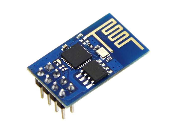
I like the Arduino development platform. Simple to programme and its support so many types of MCU. I decided to settle using ESP8266, a low cost, wifi enable MCU powerful enough for most IoT applications. The big brother ESP32 looks tempting but it cost about 3-4 time more. 

Image result for esp8266
There is a particular version of ESP8266 Wemos D1 mini which I like very much. It has a stackable design whereby various module can be stacked up without any soldering. It has quite a few models of temperature sensors, OLED display and accessories. More can be found on Wemos website.
Image result for wemos d1 mini
itead is a Chinese company which sells WIFI switches, lights and power plugs that are based on ESP8266 MCU. One unique thing about itead's sonoff range of products is it allowed flashing of custom firmware onto it. There are a few good 3rd parties firmware and I have chosen Tasmota. In the future blog post, more will be written Tasmota.

Comments

Popular posts from this blog

Using ESP-Link transparent bridge (ESP-01 and Arduino Pro Mini)

Recently stumbled across an interesting open source project ESP-Link . Its main purpose is to network-enable a non-network microcontroller (MCU) such as Arduino Uno, Pro mini or Nano using ESP8266. The author termed it as "Transparent Bridge". The ESP and MCU  communicate via the serial link and there is a companion Arduino library EL-Client  for the MCU to connect up the network using MQTT, REST, TCP and UDP. Setup I have put together an ESP-01 and an Arduino Pro Mini for this experiment. I have chosen a 3.3 version Pro mini so that I do not need to do any voltage level shifting between the I/O pins. In order to have a stable voltage source, the ESP8266 is powered by Pro Mini and the Pro Mini "RAW" pin is connected to a 5v USB power source. The RAW pin can take voltage up to 12V. The reset pin of Pro Mini is connected to GPIO 0 of ESP-01. This enables the ESP-01 to reset the Pro Mini.   I have linked up an APDS 9960 sensor to it and periodically se

DIY Sonoff RF Bridge

Tasmota recently supported the RF bridge by iTead which allowed for RF 433 remote devices to be controlled/controlling using Sonoff products. e.g A handphone can be used to control a remote RF device or an RF remote control can use to control a WIFI enabled device. By using Tasmota, I can control the device using MQTT. This idea fits exactly to my smart home plan. Here is the schematic: I cheated a bit by having ESP01 mounted on a breakout board. This breakout board converts all the external pins to 5v which simplified the wiring and I do not need to use a voltage level shifter. Moreover, the Arduino 3.3v power does not have enough current to power the ESP reliably and I have to power it via the 5V from Arduino Uno. Next, I used an Arduino Uno prototype shield with a tiny breadboard to hold all the components together. For the RF 433 transmitter/receiver, I am using the development kits when I purchased the all-in-one Arduino development kits. An antenna is added for more sensi

Using ESP-Link transparent bridge (ATmega2560+ESP8266 board)

I have found this interesting board selling on Aliexpress website. It is an Arduino Mega 2650 with a built-in ESP8266 which allows the Mega to connect to wifi. This board has cut down a lot of wiring and bring out interesting possibilities. One of this is to connect up both the microcontrollers using ESP-link firmware. I have an earlier blog post  that described how to wire up an ESP-01 and Arduino Pro Mini. One of the tricky parts in this setup is the sequence of flashing the ESP firmware. Flashing the onboard ESP8266 requires some setting changes to the dip switches. The following are the sequences which I get both the microcontrollers to talk to each other. Set the jumper 5,6,7 to ON and the rest OFF. This will set the ESP to update mode. I am using version 3.0.14  and flashed the ESP using the following parameters: esptool --port com26 --baud 230400 write_flash -fm dio -fs 4MB -ff 80m 0x0 boot_v1.6.bin 0x1000 user1.bin 0x3fc000 esp_init_data_default.bin 0x3fe0